Nikon D90. Nice machine, there is a possibility of IR remote control. Interesting: if you set the shutter speed "bulb", by pressing the shutter button it will open the shutter and by releasing it will close shutter. But if you operate the remote control, then one click opens, the following - closes. You don't need to keep the button pressed, but just click once and then - the second time. And all this without shaking, without ropes.
And another thing: noise is really low. Noise is visible in shadows, regardless of exposure. But if exposure time is long (some minutes) - there is almost no noise even in low light. And the question arises: why then the longest provided shutter is only 30 seconds?
And the second question: why the cost of the remote control ML-L3 - about $ 30-40? Although elements there cost no more than $2. I should have study economy... :)
Protocol of the channel described here and here (thanks!) and doesn't look complicated. Well, how to be complicated with just one button? :) Power of IR LED is taken by me by not so big. It turned out a range of reaction up to 8 ft at current through the LED 20 mA (do not forget: slightly, but the camera perceives infrared radiation by the main matrix. LEDs pulse (closing the shutter) can be visible in the picture). And I added also a timer. Two timers: 1) counter from zero upwards, 2) counter from the specified time down, at the end (zero) sends a IR-signal. And the usual watch. For more fantasy is not enough :).
Although if you do not put extra buttons, quartz resonator and display - it will simply analog ML-L3, however all this is necessary for initial adjustment.
Current consumption in Standby mode is small - about 10 uA. When the display turns on - around 10 mA. Therefore, the display automatically turns off after 3-4 seconds if nothing is pressed. Theoretically, CR2032 should work about 2 years (with the switched off display).
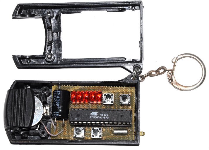
Body - from the Chinese flashlight-keychain.
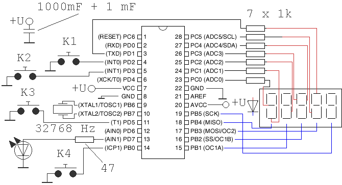
Ceramic (1 uF) is located close to the pins of the CPU power, electrolytic (100 .. 1000 uF) - from the edge of the PCB. Face value of the electrolytic capacitor: if to choose a smaller value, for example, 100 uF, it will allow to make sharper rise in voltage at the moment of battery installation, that will raise clearness of start of the processor (brownout detector is disabled to reduce power consumption). On the other hand - high value of capacity allows to use energy of a battery effectively. Although if we replace the CR2032 two AAA-size - there will never be a problem. First, try this way - two AAA-size or external power supply at 3-4 volts.
The display - from the ancient Soviet calculator, presumably ALS311A (5082-7404, 5082-7405). Inside the indicator connected to the same name anodes (different character) and cathodes of all segments of each character. Looks cool, but in light sition strongly. While in the dark (and when still need "bulb" shutter speed?) looks great. The current through it about 1 mA / segment, specifically to reduce the load on the battery.
The CPU - ATmega8L. Note the last "L" - it is important. This indicates the version of the processor for low supply voltages.
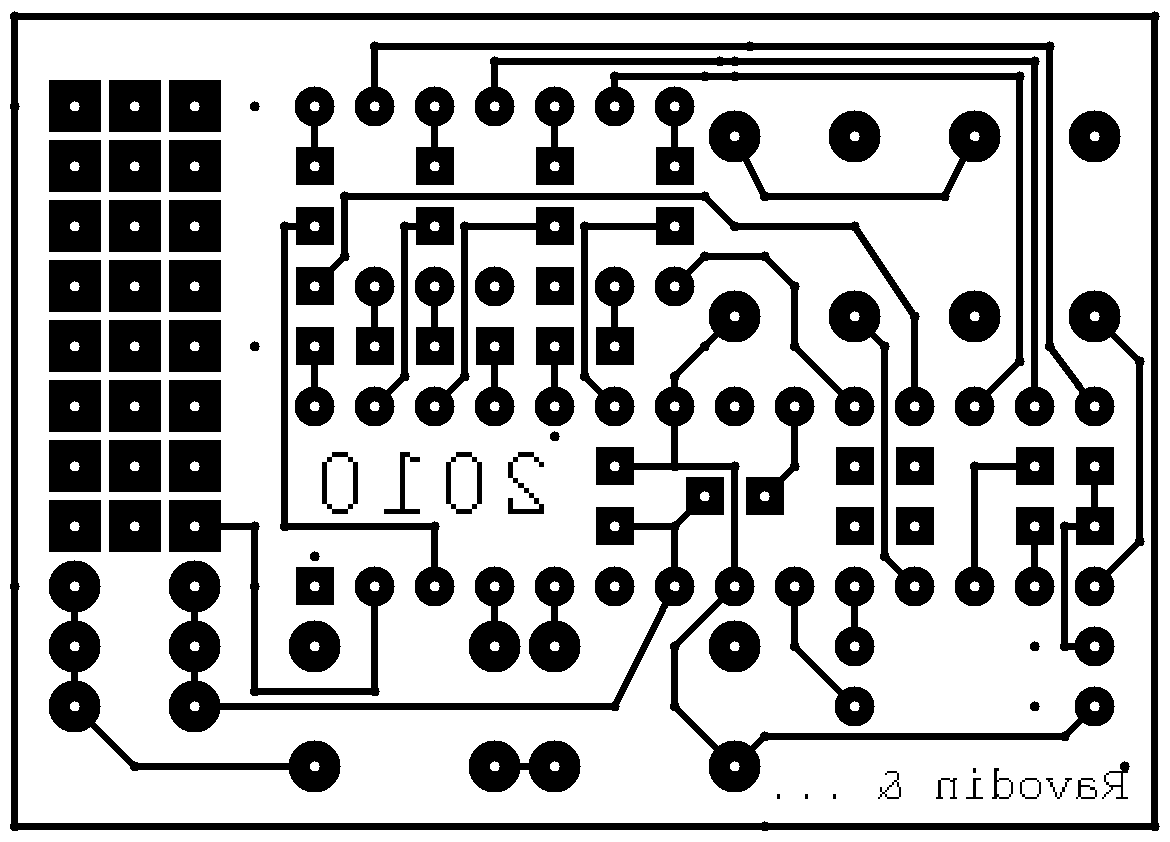
The resistors - PCB make for SMD-resistors.
Four buttons. The first toggles the menu items (if the display turned on) or send IR-command (if the display is turned off). Second - turn on / off display. The third and fourth are different in different menu items:
After assembly, power turns on and possibly force reset (pin 1 briefly connect to "ground"), pressing first button should appear in IR-flash, which you can see on the photodetector devices. You can use osciloscope parallel-connected IR-LEDs.
Scheme features: quartz resonator is used only for timers and clocks. Formation of IR commands based on an internal RC-oscillator, which should be configured to work with low supply voltage. To do this, enter the setup mode register OSCCAL (initially there will be a value set by CPU manufacturer for 5 volt) and clicking on the third and fourth buttons arises to clear triggering the camera. For example (my remote control): default value OSCCAL = 0xBA, but works fine in the range 0xAE .. 0xC8, with increasing distance range is narrowed: 0xB3 .. 0xC8. I configured my remote control in the middle of the interval - 0xBB.
Firmware can be downloaded here: it is source code, compiled code, as well as fuse's list and status.